1. Introduction
The European Union (EU) set ambitious targets to fight the issue of climate change, to guarantee the security of supply and increase competitiveness in the energy sector. The building sector, responsible for about 40% of total EU energy consumption, is a great contributor to greenhouse gas (GHG) emissions [
1]. When considering the household sector, the share of the European final energy consumption is around 26%, with about 80% due to heating, cooling, and domestic hot water production [
2]. An important step to meet the goals of reducing GHG emissions and increasing the renewable energy sources (RES) share can be obtained by adopting technologies that do not employ fossil fuels for the heating and cooling of buildings.
Heat pumps are electrical appliances that can be used for this purpose and allow an improvement in the efficiency of the energy system.
These machines can be employed when a replacement of the energy plant is needed for the retrofit of existing buildings [
3,
4]. For these applications, high-temperature heat pumps (HTHPs) can be used when heat is demanded at high-temperature levels (80–150 °C) and COP (coefficient of performance) values range between about 2.4 and 5.8 with a temperature lift of 95 to 40 °C, respectively [
5]. Traditionally, HTHPs are built using a single-stage thermodynamic cycle, representing a challenge for obtaining favorable COPs with high-temperature heat production. In the literature, studies investigating the use of new refrigerants can be found [
6,
7], highlighting the need for the adoption of fluids with low GWP (global warming potential) that show acceptable system performance at high temperature.
Other studies analyzed different machine configurations, where the thermodynamic cycle is modified to increase the efficiency and reach higher temperature levels. Dai et al. [
8] investigated five configurations of dual-pressure level condensations for exploiting waste heat, obtaining an improvement in COP of more than 9%, compared to traditional cycles. One possible layout is the cascade cycle, composed of two independent single-stage cycles, the high-temperature-stage cycle and the low-temperature-stage cycle [
9]. The two cycles are connected by an intermediate heat exchanger that works as the evaporator for the high-temperature cycle and as the condenser for the low-temperature cycle.
Fine et al. [
10] developed a numerical model of a solar-assisted cascade heat pump using photovoltaic thermal panels to provide the heat source and electricity to the system. Xu et al. [
11] presented an experimental investigation on an air-source cascade heat pump operating in cold climate conditions, demonstrating a higher efficiency in comparison to other heat solutions at low ambient temperature and in a high water-supply temperature region. Yang et al. [
12] proposed a single-fluid cascade air-source heat pump that can operate in different modes, and the analysis of the monitored data showed a linear increase in the heating capacity with the lower-stage compressor speed.
Le et al. [
13] analyzed an air-source cascade heat pump coupled with thermal storage through laboratory and field results and dynamic simulation models, finding that the heat pump can be used to obtain a CO
2 emission reduction (up to 57%) compared to the traditional boilers and obtain a seasonal COP of 2.12 with the direct heating of the retrofitted building. Mota-Babiloni et al. [
14] presented an optimization of the intermediate temperature and the internal heat exchanger effectiveness in both stage cycles of a cascade HTHP using low-GWP refrigerants, finding the maximum COP (3.15) in the combination of pentane and butane.
A different layout can be adopted by including an ejector in the thermodynamic cycle, which allows the decrease in the compression work by reducing the throttling losses and the liquid overfeeding and lifting the compressor inlet pressure [
15]. The ejector is a flow device with two intake ports and one discharge port. The primary high-pressure stream and the secondary low-pressure stream are mixed inside the ejector and discharged at some intermediate or back-pressure [
16]. Brodal and Eiksund [
17] investigated the heat pump performance with and without an ejector or a suction gas heat exchanger, as a modification to conventional transcritical CO
2-based heat pump systems. They found that for pure CO
2-based heat pumps, the systems with an ejector are more efficient than systems without, with an increase in the COP up to 19%. Liu and Lin [
18] carried out a thermodynamic analysis of an air-source heat pump producing heat at two temperature levels and using a zeotropic mixture refrigerant (R1270/R600a) of three different configurations, while Besagni et al. [
19] studied the influence of different refrigerants on ejector refrigeration systems.
A further way to enhance the efficiency of the heat pump could be to use the soil as the heat source, instead of the external air. These heat pumps are called ground-source heat pumps (GSHP) [
20,
21,
22,
23] and their advantages range from the high energy performance to environmental friendliness due to the exploitation of renewable energy sources and ease of integration with other energy systems. D’Agostino et al. [
24] compared GSHPs to air-source heat pumps or a condensing boiler coupled to a chiller to analyze the energy savings of the investigated system that reaches up to 55% for one of the two locations. Christodoulides et al. [
25] provided the cost analysis and comparisons between an air-source heat pump and a ground-source heat pump showing that, for the case study in Cyprus, the air source HP is highly competitive, while Li et al. [
26] theoretically demonstrated the general exergy convenience of GSHPs compared to air-source heat pumps.
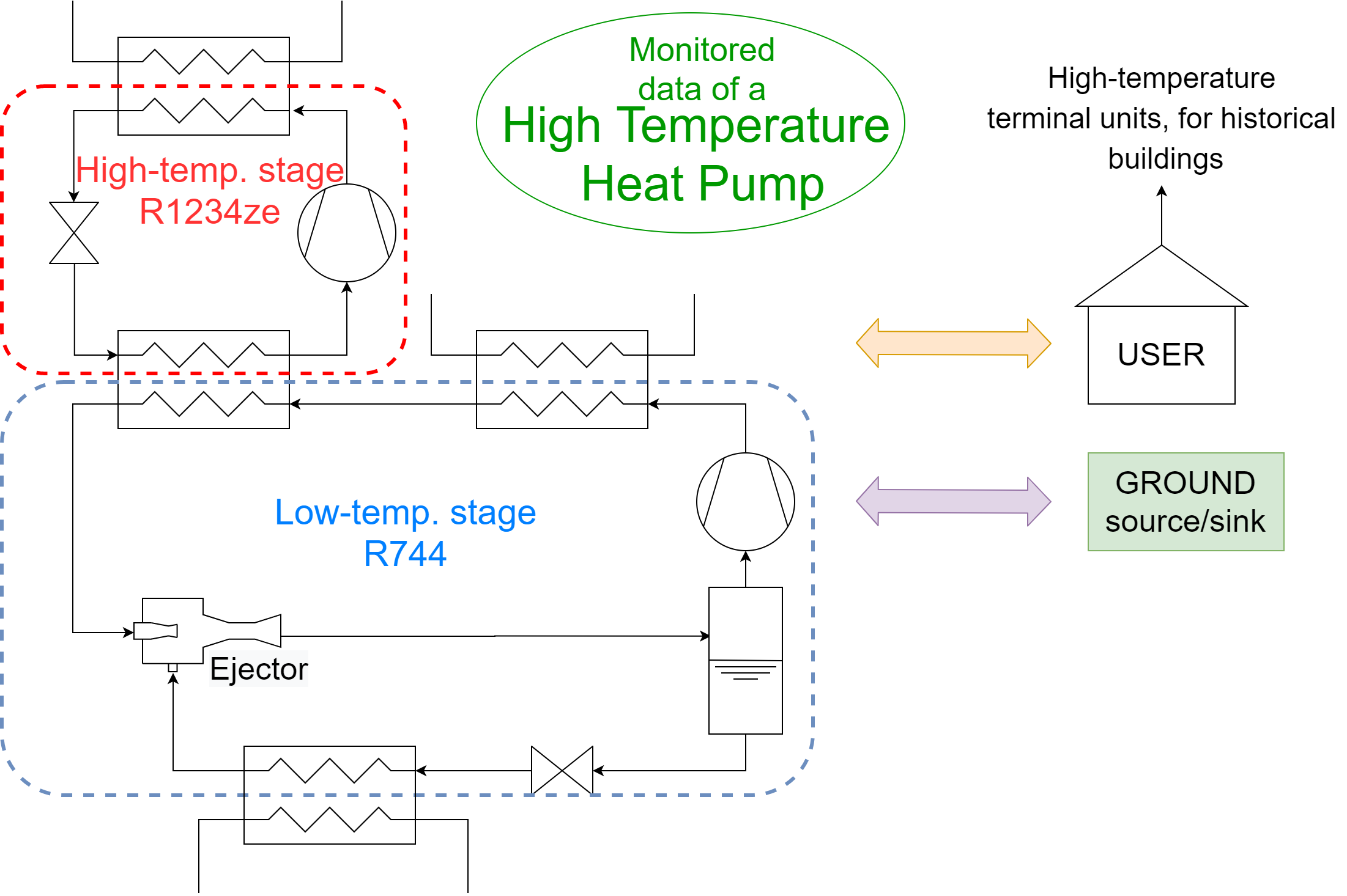
In this work, the monitored data of a novel partial cascade GSHP are presented. Indeed, the heat pump project is currently involved in a patenting process (Patent application number: 102020000021097, presented on 7th September 2020). The heat pump configuration includes an ejector and two gas-coolers in series in the low-temperature cycle, where CO2 is used as the refrigerant in a transcritical cycle. The high-temperature-stage fluid is the refrigerant R1234ze. This last cycle is not properly the high-temperature one, as the analyzed layout of the heat pump is different from a common cascade cycle as described in the following section of the text.
2. Materials and Methods
The present paper provides the description and the energy analysis of a heat pump prototype, which uses low-GWP fluids as refrigerants. Moreover, the heat pump has been developed to supply the high-temperature heat carrier fluid to the terminal units used for heating a real building in Zagreb (Croatia). The first part of the paper summarizes the main information about the case study and the details of the heat pump from the mechanical and thermodynamic points of view. In the second part of the work, the results of the operating conditions of the heat pump are described and discussed. The energy analysis has been carried out using the measured data obtained from the monitoring system installed in the plant.
2.1. The Building
The ground-source heat pump has been installed in the building that hosts the Technical Museum Nikola Tesla in Zagreb. The entire complex is listed within the National Register of Cultural Property. The building area is located in the historic city center, which is protected by a special regime of conservation and heritage protection. The building complex is enlisted within the National Register of Cultural Property, by the decision of the Ministry of Culture of the Republic of Croatia in 2005, and it is located in the historic urban areas of the city of Zagreb. The national law on the Protection and Conservation of Cultural Goods forces any structural work planned for the museum to be greenlit by the Urban Office for the Protection of Cultural and Natural Monuments. A limited part of the museum was renovated, which was an exhibition room of 380 m
2 with a volume equal to 1463 m
3, as shown in
Figure 1.
The original plant system consisted of only six electrical heaters originally used for heating, and no devices for cooling were present. This had a serious impact on the environmental comfort of both visitors and personnel with a possible threat to the fire safety of the structure, which is made mainly of wood components both in its interior and exterior.
The refurbishment intervention was approved by the museum and municipal authorities and included the installation of a CO2 heat pump with a capacity of about 30 kW. The installed heat pump is a prototype device, specifically designed to provide water at high temperature to terminals.
The refurbishment also included the drilling of a borehole heat exchanger (BHE) field consisting of six 100 m-deep BHEs in the courtyard, plus the relative hydraulic connections. In order to assure heating and cooling in the exhibition room of the museum, 10 fan coils were installed [
27].
Unlike the previous work, the present analysis investigates in detail the real behavior of the heat pump, using the data of the plant obtained from a monitoring campaign. The previous paper focused on a possible application of different management strategies for the air-conditioning of the plant and, in that context, a dynamic simulation tool was used for deriving the energy performance of the heat pump considering a mean seasonal coefficient of performance. The museum and the municipal authorities approved the retrofit of the plant after the involvement of the Museum in the Cheap-GSHP European Project [
27].
2.2. The Thermal Power Plant
The reversible heat pump is a water-to-water machine that uses a geothermal field as the source and sink in heating and cooling operation, respectively. It consists of two cycles: The low-temperature cycle uses the natural fluid CO2 as the refrigerant, and the high-temperature cycle uses the hydrofluoro-olefin (HFO) refrigerant R1234ze.
The design of this machine came from the necessity to develop and build a heat pump generation system suitable for a retrofit application, where the heat carrier fluid is required at high-temperature levels, to be used in existing terminal units. As the existing terminal units were electric in the analyzed case study, the use of the heat pump presented several advantages. Indeed, the heat pump reduces the electric energy demand and, at the same time, can produce chilled water to cool the exhibition room in summer, while in the previous configuration, the building was not provided with a cooling system. The solution proposed in the present work is suitable for buildings characterized by a dominant heating thermal load profile. Usually, commercial heat pumps can be used for cooling, through the use of a four-way valve in the refrigerant circuit that reverses the thermodynamic cycle (the component that was used as the condenser is used as the evaporator). On the contrary, in this study, as the heat pump has a double cycle in cascade, the switch of the operating mode is obtained by changing the hydraulic circuit side, not the refrigerant circuit.
The switch of the operation mode, heating and cooling, is allowed using the two 4-way valves and is highlighted in the two schemes of
Figure 2. The figure shows the connections of the thermal power plant located outside the building, inside a dedicated room used by the Museum as a showroom for didactic visits. The plant is divided into four main parts: The heat pump, the hydronic module, the borehole heat exchanger (BHE) field, and the distribution pipelines.
The refurbishment of the thermal power plant also included the drilling of a BHE field, consisting of six 100 m-deep ground heat exchangers positioned in the garden and the relative horizontal hydraulic connections. In order to assure heating and cooling provision to the exhibition room of the museum, 10 fan coils were installed. The fluid that circulates in the BHE field is a mixture of pure water and antifreeze. For ground-source heat pump applications, the antifreeze is normally used to prevent the freezing of the horizontal connections during the stop of the thermal power plant, or to prevent the damaging of the plant and of the heat pump when the borehole field is not properly designed and the ground is affected by thermal drift.
2.3. The Heat Pump
As can be seen from the scheme in
Figure 2, the heat pump configuration differs from the more common double cascade thermodynamic cycles that can usually be found in the market. The heat carrier fluid exchanges heat with the two thermodynamic cycles by the use of two flat plate heat exchangers connected in series, while usually, the double cascade cycles use only one heat exchanger at the condenser side of the high-temperature cycle. For this reason, the configuration in the figure could be defined as a “partial” double cascade cycle. In the market, high-temperature transcritical heat pumps that use CO
2 as the refrigerant are quite common, but among the main limits of these machines, the high values of temperature difference required at the condenser side limit the achievement of good energy performances. Consequently, the terminal units used for heating should work with low flow rates and high temperature drops to go below the critical temperature of the CO
2. As widely known in the air-conditioning field, the only terminal units that can work below the critical temperature are radiant systems. However, in these applications, the temperature drops do not exceed 3–4 °C, as suggested by the standards, in order to guarantee a uniform temperature of the radiant surface and good thermal comfort for the users. The layout of the heat pump prototype allows this last problem that limits the use of the transcritical cycle in the field of air conditioning of buildings to be overcome.
In this case study, the heat pump exploits the advantages of the medium/high-temperature cycle, using the CO
2 refrigerant in the transcritical cycle and the heat exchanged at high temperature by the subcritical cycle, which uses the R1234ze refrigerant. The total heat flux exchanged with the heat carrier fluid is the sum of the heat flux exchanged at the gas cooler of the CO
2 transcritical cycle and the heat flux exchanged at the condenser of the high-temperature cycle working with the HFO refrigerant. As is well known, the CO
2 is not suitable for every application in refrigeration, air-conditioning, and heat pump systems, and it presents some limitations in order to guarantee good energy performance. The CO
2 has a vapor pressure much higher than other traditional refrigerant fluids and its critical temperature is around 31 °C. This last characteristic leads to the impossibility of discharging heat to the external air through condensation in a subcritical cycle, when the air temperature, or in general, the heat carrier fluid, is above the critical temperature. The main consequence is that CO
2 can be used efficiently for cooling applications when heat is discharged below the critical temperature, while at higher temperatures, when the cycle works at supercritical pressures, only gas cooling is possible. Therefore, in cooling applications, the use of the ground as the heat sink is a possible and efficient solution. On the other hand, when the heat pump operates in heating mode, the HVAC (Heating Ventilation Air Conditioning) applications could result more complex because, generally, the supply temperature for the terminal units is above 30 °C, except for radiant systems. However, CO
2 is a natural fluid, its ODP (ozone depletion potential) is null, it is not flammable and not toxic (A1), and its GWP is equal to 1. For this reason, CO
2 was also used in the past when environmental advantages and safety restrictions reasons overcame the energy drawbacks. The R1234ze refrigerant is an alternative fluid to the R134a and its environmental impact is lower if compared to the latter. The main properties of the two refrigerants are summarized in
Table 1.
The thermodynamic cycles of the heat pump are represented in
Figure 3 in a temperature–entropy chart. The diagram shows, from a qualitative point of view, the operating points of the thermodynamic cycles during the heat pump operations. The letters and the numbers in the chart refer to the points reported in
Figure 2, which shows the scheme of the heat pump’s high and low-temperature cycles.
The properties of the main components of the heat pump are summarized in
Table 2. The heat pump is a prototype because it is not available in the market yet, even though all the devices constituting the machine are employed in other applications. For example, the ejector used in the CO
2 cycle is not commonly used in HVAC application, but rather in commercial refrigeration. One of the main objectives during the development of this prototype was to investigate the energy performance potential of this technology at the time of the project. In the last two years, the HVAC market started to introduce new devices and components properly developed for HVAC applications that use the CO
2 as the refrigerant. These new products can certainly guarantee better results than those obtained with the technology available about 3–4 years ago and used in the prototype; therefore, the results of this study can be considered the starting point of this emerging technology. The investigated heat pump was thought to be used in plug-and-play applications, as the generation module and the hydraulic module have been included in a common box. The control of the heat pump works at two levels: The high-temperature stage is controlled by the regulation system that keeps the gas cooler outlet temperature at a setpoint value of 35 °C, with a dead band of 5 °C. If the temperature drops below 30 °C, the thermal efficiency of the high stage cycle decreases under acceptable values as the evaporating temperature is too low. However, the dead band of 5 °C prevents the continuous on/off of the HFO compressor. The compressor of the CO
2 sets its working conditions by monitoring the return temperature of the heating and cooling terminal units. The volume flow rate of the BHE field circuit is modified according to the following principles: In heating mode, when the evaporator supply temperature decreases, the flow rate increases, and the control is done evaluating a set point evaporator pressure; in cooling mode, the flow rate is modified by keeping a constant temperature difference between the inlet and the outlet at the evaporator side. The volume flow rate at the user side of the heat pump is set to maintain a constant temperature difference between the supply and return temperatures of the circuit, to 5 °C and 10 °C in cooling mode and heating mode, respectively.
2.4. The Monitoring System
The monitoring system consists of flow meters and temperature probes for the measurement of the heat fluxes exchanged between the heat carrier fluids and the refrigerants, at the user side (fan coil terminal units) and source side (ground heat exchangers field), respectively. Other parameters have been monitored in the thermodynamic cycle in order to evaluate the behavior of the cycle during the operation of the system. In particular, considering the CO2 cycle, the pressures of the refrigerant inside the gas cooler (GC) and inside the evaporator (EV) have been logged by the system. The electrical consumption of the heat pump, necessary for the evaluation of the COP and EER (Energy Efficiency Ratio), has been measured using two energy meters. The first electricity meter monitored the electrical energy demanded by the compressors and the auxiliary devices of the heat pump. These consisted of the auxiliary electric resistances present in the heat pump for the safety of the components during the stop of the plant in the heating period, in the unit controller and in other electric minor devices present inside the heat pump box. The second is located in the hydronic module of the thermal power plant, which has two pumps (user and source side). The electrical energy meter measures their energy consumption and the demand of the controller, which manages the operation of this system. As for the first energy meter, a small part of the total electrical energy consumption is due to other devices located in the hydraulic box, installed in the thermal power plant of the Museum.
The main properties of the monitoring units installed in the thermal power plant are summarized in
Table 3. The experimental uncertainty of the measurement chain is within ±10% for the analyzed case study. The time step of the logging data has been set to 30 s.
4. Results and Discussion
In this section, the data of the monitoring campaign are discussed in detail, evaluating the behavior of the system from the thermal and electrical points of view. The operating conditions for some selected days and the energy fluxes involved in the system have been investigated. In particular, the heating mode and the cooling mode of the heat pump were considered. Some days have been chosen and analyzed considering the days with continuous operation and the days with only a few starts of the heat pump during the day.
In
Figure 6, the trend of the system’s temperatures and R744 pressures are represented for 18 November 2018. This is a representative day of continuous operation mode in heating. In particular, the chart shows the heat carrier fluid temperatures at the inlet and outlet of the high-temperature heat exchangers and the heat carrier fluid temperatures at the inlet and outlet of the evaporator coupled with the BHE field. The temperatures of the fluids have been measured in the points of the system, as represented in the scheme of the thermal power plant in
Figure 2. The switch-on of the heat pump is controlled by the value of the temperature of the fluid in the thermal storage tank (T
tank). The setpoint temperature of the storage tank is 67.5 °C with an upper dead band of 1.5 °C, so the heat pump is shut down when the temperature of the storage tank is higher than 69 °C. As can be seen in the chart during this day, the system works continuously, the heat pump starts for 29 times, and each on and off cycle lasts about 50 min. The pressure of the R744 transcritical cycle is shown in
Figure 6b. The high pressure (HP—Point 3 of the scheme in
Figure 2) of the cycle at the gas cooler varies between 95 and 80 bar while the low pressure (LP—Point 9 of the scheme in
Figure 2) and suction pressure (SP—Point 6 of the scheme in
Figure 2) at the compressor vary between 40 and 50 bar. A zoom of the on and off cycle of the heat pump is reported in
Figure 7. In the charts, temperatures and pressures between 6:28 a.m. and 7:26 a.m. are reported. At the beginning of the on and off cycle, the high pressure rises to the maximum value, decreasing gradually until the stop of the heat pump when the setpoint temperature of the storage tank was reached. As can be seen in the chart in
Figure 7a, before and during the first part of the cycle, the values of T
inwg_gc + cd and T
outwg_gc + cd were the same. This happens because the heat pump compressor was off until 6:37 a.m., but the circulator of the hydronic module started about two minutes before the compressor. Indeed, the compressor has a time delay of switch-on after the start of the circulator for safety and protection of the components of the heat pump. The details of the pressures of the R744 cycle are reported in
Figure 7b. As can be seen in the chart, the SP and evaporator pressure (LP) are the same during the operation of the heat pump, as expected, while the SP is equal to the HP when the compressor is off because the two pressures are in equilibrium through the compressor. The LP is less than the other pressures because of the expansion valves present in the refrigerant loop.
In
Figure 8,
Figure 9,
Figure 10 and
Figure 11, similar charts are presented for two representative days in December. As for 4 December 2018, the plant was working for 14.9 h, providing water to the storage tank at 67.8 °C on average. From the graph in
Figure 8a, it can be noticed that the switching-on cycles were less frequent in the warmer hours of the day (the external air temperature is also shown in this figure). In this case, the high pressure of the cycle at the gas cooler also varied between 95 and 80 bar, while the low pressure and suction pressure at the compressor varied between 40 and 50 bar.
Similar considerations can be done for 29 December 2018, when the heat pump results to be operating nearly without interruptions. In this case, the electrical energy demanded by the compressors of the heat pump compressors during the whole day is 291 kWh, nearly 56% more than for the day of 4 December. In the same way, the electrical energy absorbed by the auxiliaries is nearly three times with 29 against 11 kWh for the day of 4 December. In addition, the thermal energy released at the user-side of the HP and withdrawn from the ground is about 54% higher for 29 December, with an amount of 631 and 350 kWh, respectively. As shown in
Figure 11b, the high pressure of the cycle at the gas cooler varies between 80 and 85 bar, while the low pressure and suction pressure at the compressor are between 35 and 40 bar. In this last case, the values of LP are lower than the other two days because of the lower temperature of the heat source that affects the evaporating temperature and the relative pressure at the evaporator side. As can be seen in the charts, the inlet temperature of the heat carrier fluid at the evaporator moves from about 11 °C to about 8 °C. On the other hand, at the gas cooler, the steady-state pressure after the first phase of the switching-on of the heat pump is about 80 bar. This is due to the control system that regulates the outlet temperature at the gas cooler at 35 °C, as previously described in the Heat Pump section of the text.
Considering the months of November and December, the temperature of the water entering the condenser at the user side of the heat pump is about 60 °C and 63 °C, respectively. The water is then heated up to 67/71 °C, maintaining an average storage tank temperature of 67.5 °C. At the source side of the heat pump, the heat carrier fluid from the BHE field loop has a monthly average temperature of 13.5 °C in November and 8.4 °C in December. The fluid is then cooled inside the evaporator to 9 °C and 6 °C in November and December, respectively.
In
Table 4, the values for the heat pump COP and for the system COP, for the investigated days in November and December, and for the selected on-off cycle of the heat pump are shown.
The
COPHP of the heat pump is defined as the thermal energy delivered at the user-side of the heat pump (
Q1), divided by the electrical energy absorbed by the compressors of the low (
Pcomp,L) and high-temperature cycles (
Pcomp,H). On the other hand, the
COPsys of the system is defined as the thermal energy delivered at the user-side of the heat pump (
Q1), divided by the electrical energy absorbed by the compressors of the low and high-temperature cycles (
Pcomp,H +
Pcomp,L) and by the auxiliaries of the hydronic system (
Paux).
During these days, the source temperatures are 12 °C, 9.5 °C, and 7.1 °C for November and 4 and 29 December.
In cooling mode, the cycle working with R1234ze is off and only the CO2 thermodynamic cycle is switched on. The hydronic module modifies its layout by changing the position of the two 4-way valves. In this configuration, the BHE field loop exchanges heat with the gas cooler heat exchanger while the user tank exchanges heat with the evaporator heat exchanger. Unlike the heating mode, the pressures of the CO2 cycle are different because the high pressure (HP) is set by the controller of the heat pump in order to obtain the optimal value, which is a function of the outlet temperature at the gas cooler heat exchanger. Therefore, in this case, the pressure depends on the temperature of the heat carrier fluid in the BHE field loop. Similarly, as shown for the heating mode, few days have been analyzed in detail to show the behavior of the heat pump from the temperature and pressure point of views.
In particular, the temperature profile and the operating pressures of the cycle have been analyzed for one day in June, July, and August. Moreover, the one on-off cycle of the heat pump can be seen in detail for each representative day.
The temperature of the water entering the evaporator and, therefore, at the user side of the heat pump is about 7.4 °C for the months of June and July, while it is an average of 7 °C in August. On the other hand, the temperature exiting the evaporator is set to 6 °C. Considering the source side of the heat pump, the temperature of the heat carrier fluid coming from the BHE field loop is around 17.7 °C in June on a monthly average, 18.8 °C in July, and 17.3 °C in August. Respectively, inside the gas cooler, its temperature is increased to 23.2 °C, 24.3 °C, and 22.4 °C.
The average monthly temperature of the water inside the storage tank is 6.6 °C in June, and 6.9 °C in July and August.
In
Figure 12,
Figure 13,
Figure 14,
Figure 15,
Figure 16 and
Figure 17, the trends of the system’s temperatures and R744 pressures are represented for 29 June, 19 July, and 22 August 2018. The charts show the heat carrier fluid temperatures at the inlet and outlet of the evaporator at the user-side of the HP and the heat carrier fluid temperatures at the inlet and outlet of the condenser coupled with the BHE field.
The representative day for June was 29, when the heat pump was on nearly 9 h. The high pressure of the cycle at the gas cooler varied between 45 and 70 bar while the low pressure and suction pressure were in the range of 25 and 50 bar, as for the other analyzed summer days.
Table 5 summarizes the EER values for the heat pump and for the heat pump coupled with the hydronic system, for the investigated days in June, July, and August, and for the selected on-off cycle of the heat pump.
The EER of the heat pump is defined as the thermal energy withdrawn at the user-side of the heat pump (Q
2), divided by the electrical energy absorbed by the compressor of the CO
2 cycle (P
comp,L). On the other hand, the EER of the system is defined as the thermal energy withdrawn at the user-side of the heat pump (Q
2), divided by the electrical energy absorbed by the compressor of the low-temperature cycles (P
comp,L) and by the auxiliaries of the hydronic system (P
aux).
During these days, the source temperatures are 18 °C, 19.4° C, and 19.6 °C for June, July, and August, respectively, and it can be seen that higher source temperatures lead to lower EER values.
From the monitoring campaign, the EER and COP of the heat pump and of the entire system were evaluated. In particular, when considering the operation during the month of July, a heat pump EER of 3.55 and a system EER of 2.74 have been found. As for the heating operation, in December, the heat pump COP was 2.15, while the system COP was 2.01.

 ,
, 


