Microemulsion vs. Precipitation: Which Is the Best Synthesis of Nickel–Ceria Catalysts for Ethanol Steam Reforming?


 , and
, and
Abstract
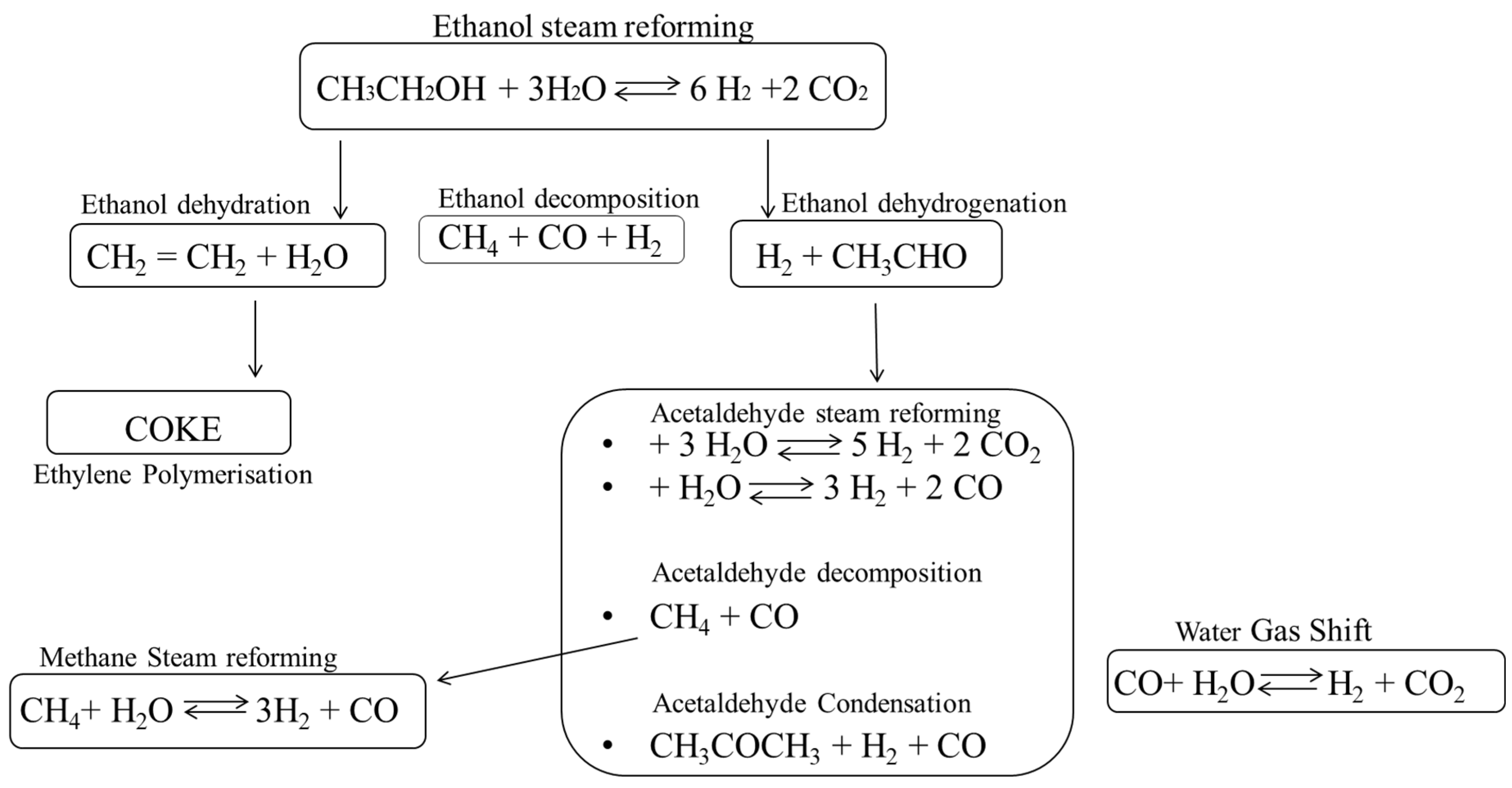
:1. Introduction
2. Experimental Part
2.1. Support Preparation
2.2. Catalyst Preparation
2.3. Catalysts Characterization
2.4. Catalytic Tests
3. Results and Discussion
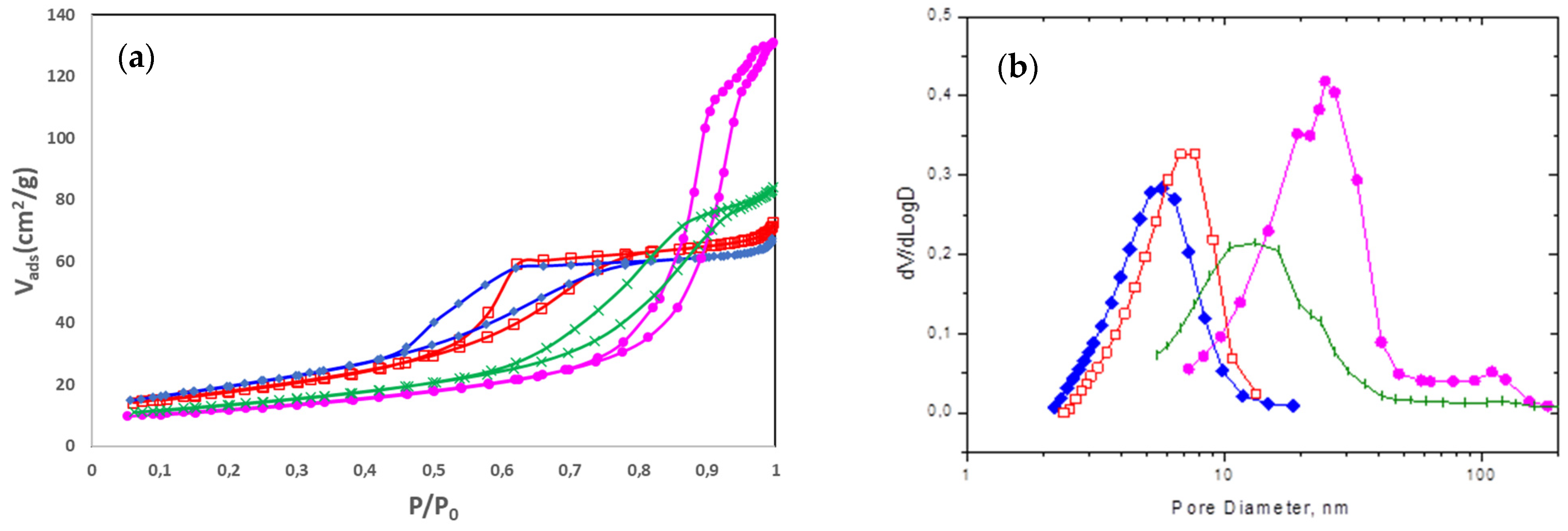
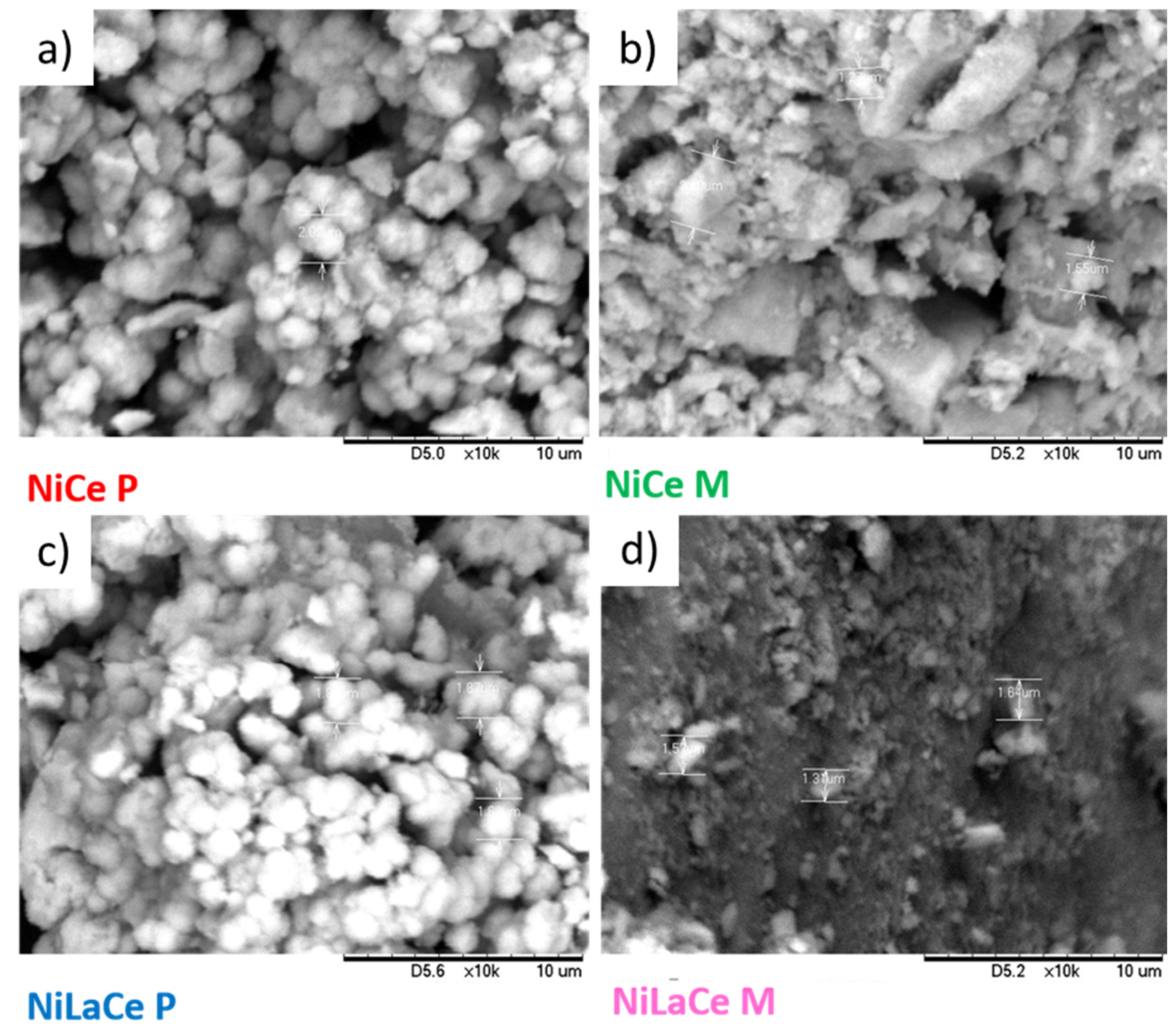
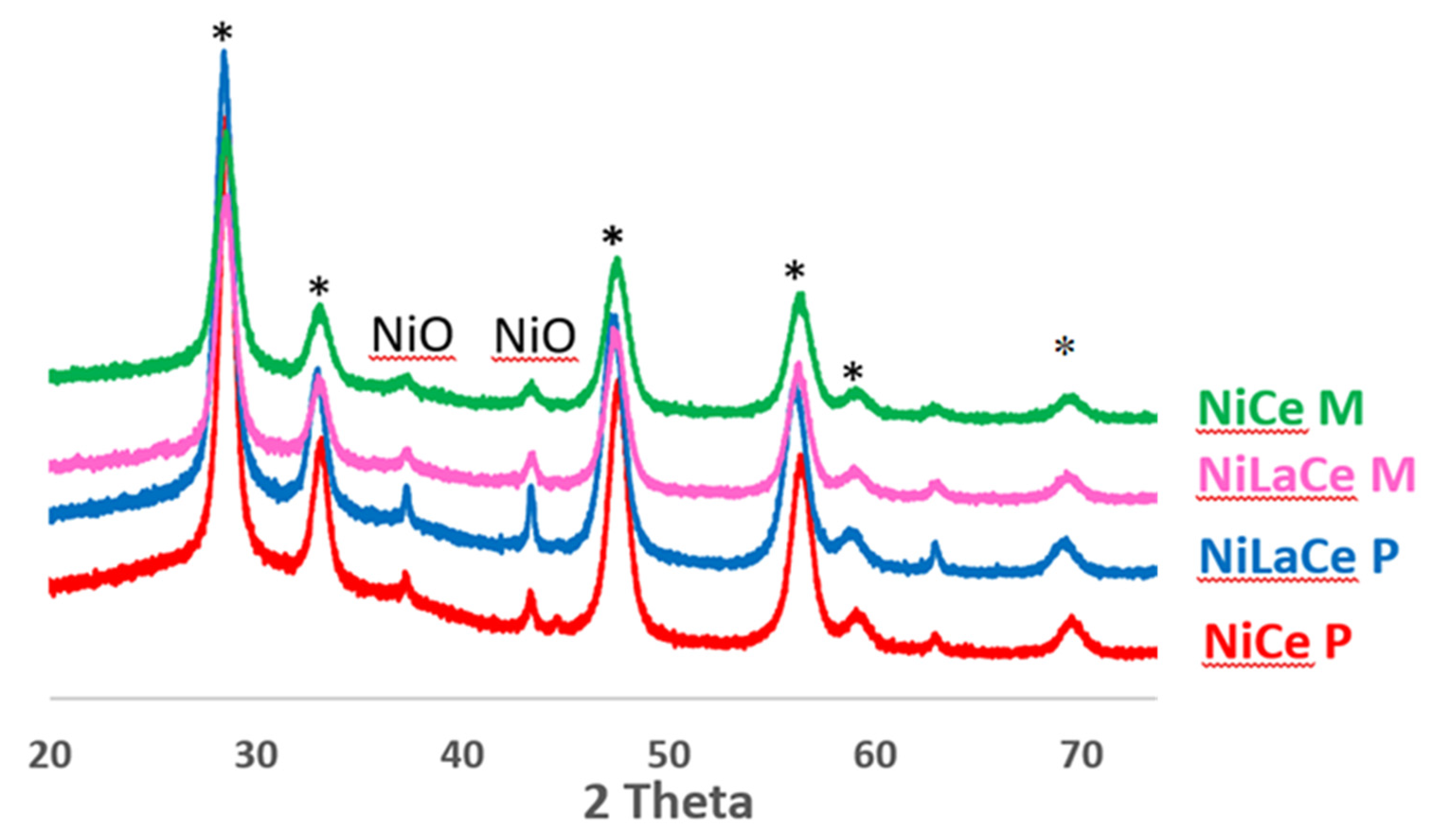
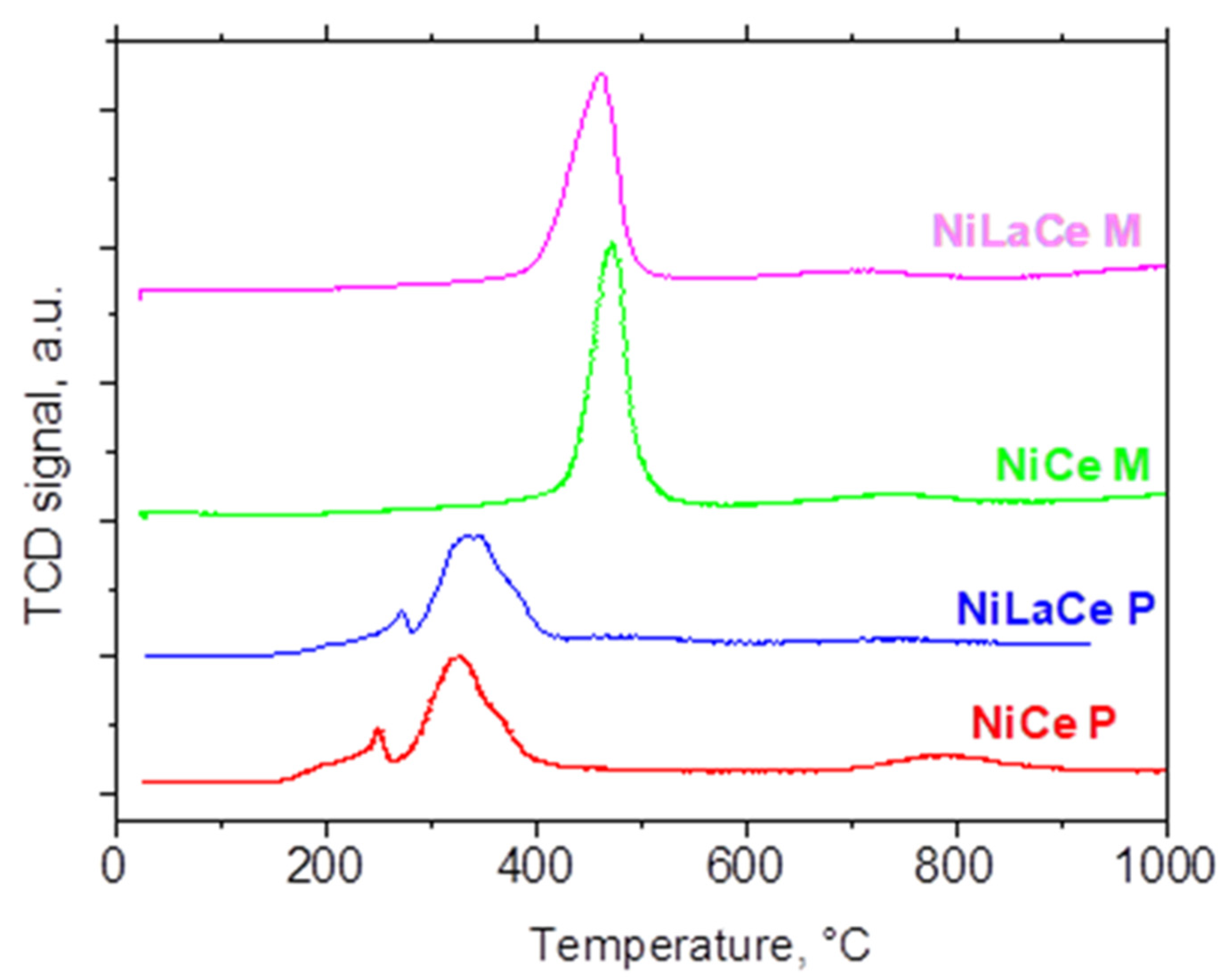
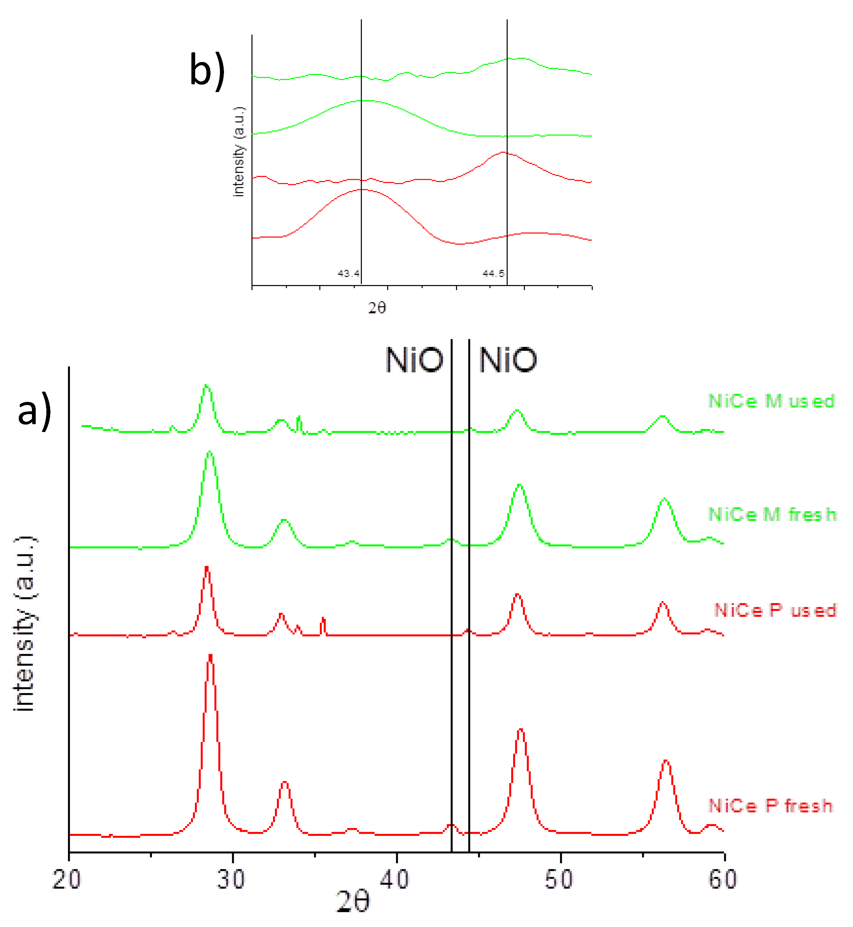
3.1. Catalysts Characterization
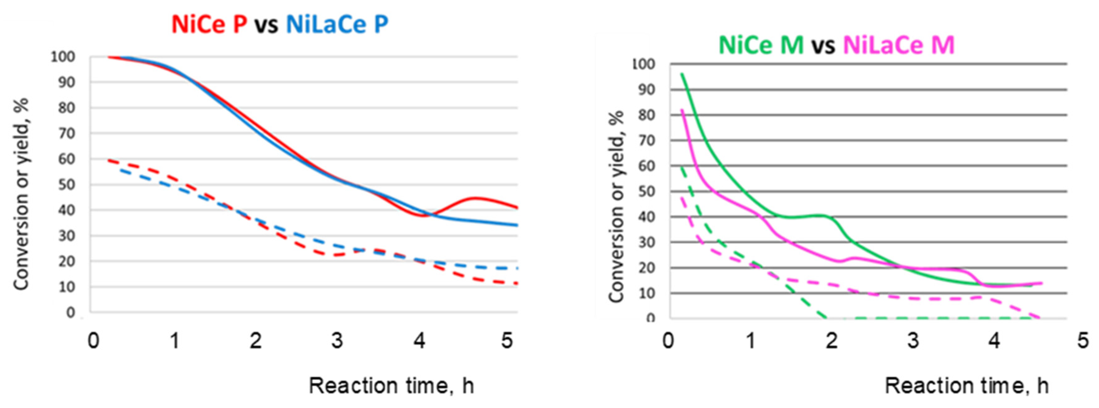
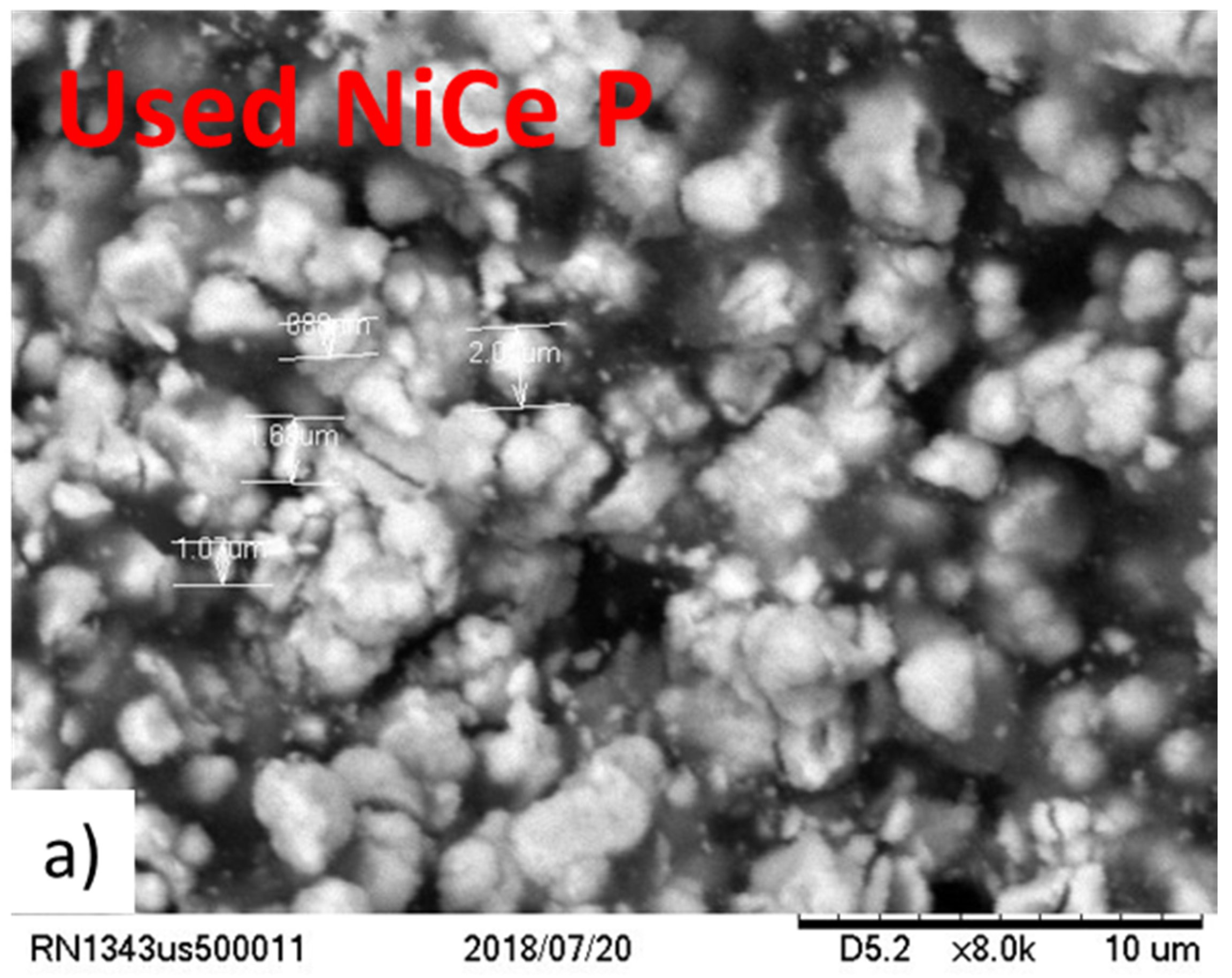
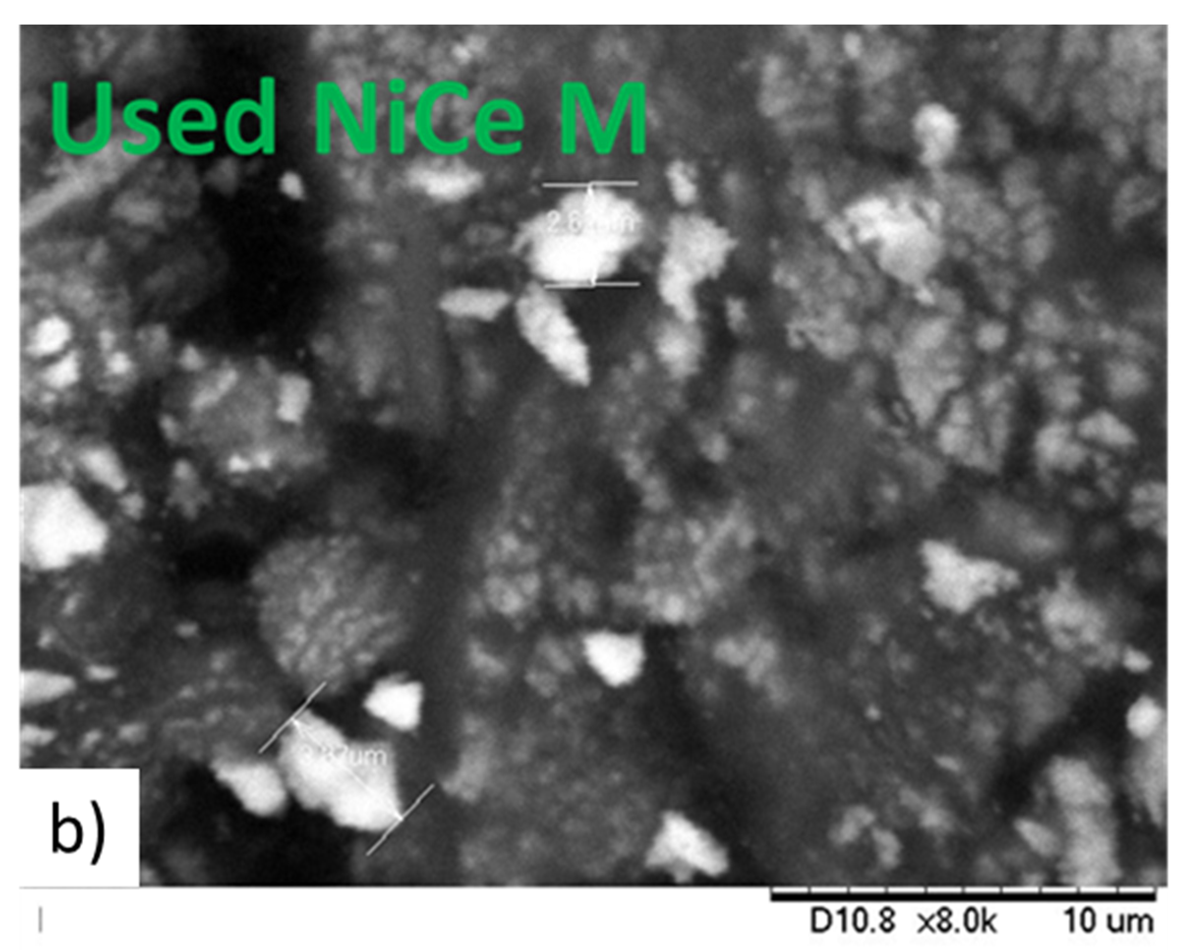
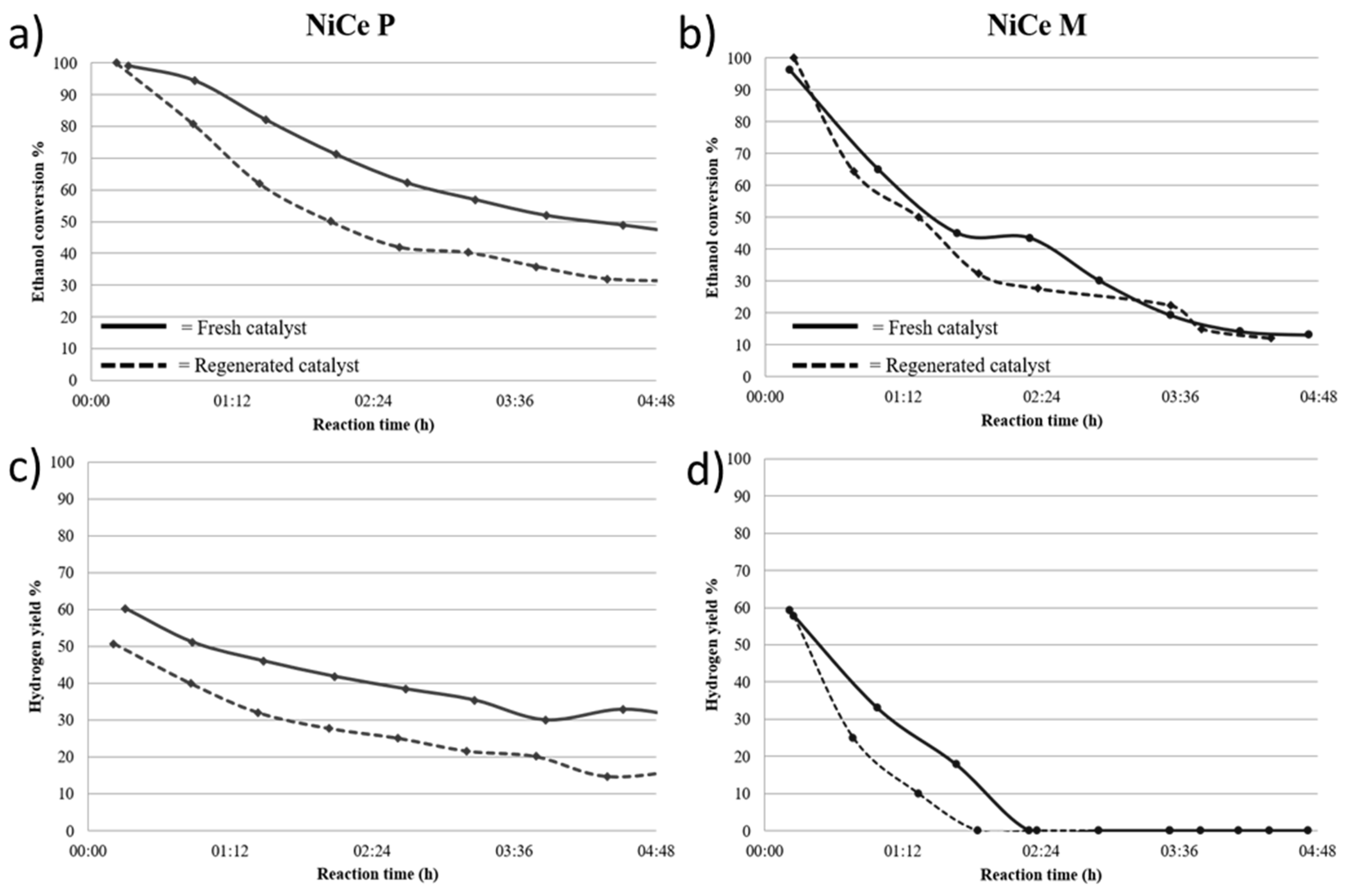
3.2. Catalytic Performances
4. Conclusions
Author Contributions
Funding
Acknowledgments
Conflicts of Interest
References
- IEA. The Future of Hydrogen, IEA, Paris. Available online: https://www.iea.org/reports/the-future-of-hydrogen (accessed on 12 November 2020).
- Wang, J.; Chen, H.; Tian, Y.; Yao, M.; Li, Y. Thermodynamic analysis of hydrogen production for fuel cells from oxidative steam reforming of methanol. Fuel 2012, 97, 805–811. [Google Scholar] [CrossRef]
- Ball, M.; Weeda, M. The hydrogen economy—Vision or reality? Int. J. Hydrogen Energy 2015, 40, 7903–7919. [Google Scholar] [CrossRef]
- Navarro, R.M.; Peña, A.M.A.; Fierro, J.G. Hydrogen Production Reactions from Carbon Feedstocks: Fossil Fuels and Biomass. Chem. Rev. 2007, 107, 3952–3991. [Google Scholar] [CrossRef]
- Abe, J.; Popoola, A.; Ajenifuja, E.; Popoola, O. Hydrogen energy, economy and storage: Review and recommendation. Int. J. Hydrogen Energy 2019, 44, 15072–15086. [Google Scholar] [CrossRef]
- Gallucci, F.F.; Basile, A.A.; Tosti, S.; Iulianelli, A.; Drioli, E. Methanol and ethanol steam reforming in membrane reactors: An experimental study. Int. J. Hydrogen Energy 2007, 32, 1201–1210. [Google Scholar] [CrossRef]
- Liu, Z.; Senanayake, S.D.; Rodriguez, J.A. Catalysts for the Steam Reforming of Ethanol and Other Alcohols. Ethanol 2019, 574, 133–158. [Google Scholar] [CrossRef]
- Martinelli, M.; Watson, C.D.; Jacobs, G. Sodium doping of Pt/m-ZrO2 promotes C–C scission and decarboxylation during ethanol steam reforming. Int. J. Hydrogen Energy 2020, 45, 18490–18501. [Google Scholar] [CrossRef]
- Mironova, E.; Lytkina, A.; Ermilova, M.; Efimov, M.N.; Zemtsov, L.; Orekhova, N.; Karpacheva, G.; Bondarenko, G.; Muraviev, D.; Yaroslavtsev, A.B. Ethanol and methanol steam reforming on transition metal catalysts supported on detonation synthesis nanodiamonds for hydrogen production. Int. J. Hydrogen Energy 2015, 40, 3557–3565. [Google Scholar] [CrossRef]
- Mattos, L.V.; Jacobs, G.; Davis, B.H.; Noronha, F.B. Production of Hydrogen from Ethanol: Review of Reaction Mechanism and Catalyst Deactivation. Chem. Rev. 2012, 112, 4094–4123. [Google Scholar] [CrossRef]
- Słowik, G.; Greluk, M.; Rotko, M.; Machocki, A. Evolution of the structure of unpromoted and potassium-promoted ceria-supported nickel catalysts in the steam reforming of ethanol. Appl. Catal. B Environ. 2018, 221, 490–509. [Google Scholar] [CrossRef]
- Xu, W.; Liu, Z.; Johnston-Peck, A.C.; Senanayake, S.D.; Zhou, G.; Stacchiola, D.; Stach, E.A.; Rodriguez, J.A. Steam Reforming of Ethanol on Ni/CeO2: Reaction Pathway and Interaction between Ni and the CeO2 Support. ACS Catal. 2013, 3, 975–984. [Google Scholar] [CrossRef]
- Rodrigues, T.S.; E Silva, F.A.; Candido, E.G.; Da Silva, A.G.M.; Geonmonond, R.D.S.; Camargo, P.H.C.; Linardi, M.; Fonseca, F. Ethanol steam reforming: Understanding changes in the activity and stability of Rh/MxOy catalysts as function of the support. J. Mater. Sci. 2019, 54, 11400–11416. [Google Scholar] [CrossRef]
- Arslan, A.; Doğu, T. Effect of calcination/reduction temperature of Ni impregnated CeO2–ZrO2 catalysts on hydrogen yield and coke minimization in low temperature reforming of ethanol. Int. J. Hydrogen Energy 2016, 41, 16752–16761. [Google Scholar] [CrossRef]
- Montero, C.; Remiro, A.; Benito, P.L.; Bilbao, J.; Gayubo, A.G. Optimum operating conditions in ethanol steam reforming over a Ni/La2O3-αAl2O3 catalyst in a fluidized bed reactor. Fuel Process. Technol. 2018, 169, 207–216. [Google Scholar] [CrossRef]
- Di Michele, A.; Dell’Angelo, A.; Tripodi, A.; Bahadori, E.; Sànchez, F.; Motta, D.; Dimitratos, N.; Rossetti, I.; Ramis, G.; Sanchez, F. Steam reforming of ethanol over Ni/MgAl2O4 catalysts. Int. J. Hydrogen Energy 2019, 44, 952–964. [Google Scholar] [CrossRef] [Green Version]
- Compagnoni, M.; Tripodi, A.; Di Michele, A.; Sassi, A.P.; Signoretto, M.; Rossetti, I. Low temperature ethanol steam reforming for process intensification: New Ni/MOx–ZrO2 active and stable catalysts prepared by flame spray pyrolysis. Int. J. Hydrogen Energy 2017, 42, 28193–28213. [Google Scholar] [CrossRef]
- Wu, Z.; Li, M.; Overbury, S.H. On the structure dependence of CO oxidation over CeO2 nanocrystals with well-defined surface planes. J. Catal. 2012, 285, 61–73. [Google Scholar] [CrossRef]
- Manzoli, M.; Avgouropoulos, G.; Tabakova, T.; Papavasiliou, J.; Ioannides, T.; Boccuzzi, M.M.A.F. Preferential CO oxidation in H2-rich gas mixtures over Au/doped ceria catalysts. Catal. Today 2008, 138, 239–243. [Google Scholar] [CrossRef]
- Pizzolitto, C.; Menegazzo, F.; Ghedini, E.; Innocenti, G.; Di Michele, A.; Cruciani, G.; Cavani, F.; Signoretto, M. Increase of Ceria Redox Ability by Lanthanum Addition on Ni Based Catalysts for Hydrogen Production. ACS Sustain. Chem. Eng. 2018, 6, 13867–13876. [Google Scholar] [CrossRef]
- Aneggi, E.; Boaro, M.; Colussi, S.; de Leitenburg, C.; Trovarelli, A. Ceria-Based Materials in Catalysis: Historical Perspective and Future Trends. In Handbook on the Physics and Chemistry of Rare Earths; Elsevier: Amsterdam, The Netherlands, 2016. [Google Scholar] [CrossRef]
- Menegazzo, F.; Pizzolitto, C.; Ghedini, E.; Di Michele, A.; Cruciani, G.; Signoretto, M. Development of La Doped Ni/CeO2 for CH4/CO2 Reforming. C 2018, 4, 60. [Google Scholar] [CrossRef] [Green Version]
- Laguna, O.H.; Centeno, M.A.; Boutonnet, M.; Odriozola, J.A. Au-supported on Fe-doped ceria solids prepared in water-in-oil microemulsions: Catalysts for CO oxidation. Catal. Today 2016, 278, 140–149. [Google Scholar] [CrossRef]
- Elias, J.S.; Risch, M.; Giordano, L.; Mansour, A.N.; Shao-Horn, Y. Structure, Bonding, and Catalytic Activity of Monodisperse, Transition-Metal-Substituted CeO2Nanoparticles. J. Am. Chem. Soc. 2014, 136, 17193–17200. [Google Scholar] [CrossRef] [PubMed]
- Ferencz, Z.; Erdőhelyi, A.; Baán, K.; Oszkó, A.; Óvári, L.; Kónya, Z.; Papp, C.; Steinrück, H.-P.; Kiss, J. Effects of Support and Rh Additive on Co-Based Catalysts in the Ethanol Steam Reforming Reaction. ACS Catal. 2014, 4, 1205–1218. [Google Scholar] [CrossRef] [Green Version]
- Eriksson, S.; Nylén, U.; Rojas, S.; Boutonnet, M. Preparation of catalysts from microemulsions and their applications in heterogeneous catalysis. Appl. Catal. A Gen. 2004, 265, 207–219. [Google Scholar] [CrossRef]
- Brunauer, S.; Emmett, P.H.; Teller, E. Adsorption of Gases in Multimolecular Layers. J. Am. Chem. Soc. 2005, 60, 309–319. [Google Scholar] [CrossRef]
- Barrett, E.P.; Joyner, L.G.; Halenda, P.P. The Determination of Pore Volume and Area Distributions in Porous Substances. I. Computations from Nitrogen Isotherms. J. Am. Chem. Soc. 1951, 73, 373–380. [Google Scholar] [CrossRef]
- Rossetti, I.; Lasso, J.; Nichele, V.; Signoretto, M.; Finocchio, E.; Ramis, G.; Di Michele, A. Silica and zirconia supported catalysts for the low-temperature ethanol steam reforming. Appl. Catal. B Environ. 2014, 150–151, 257–267. [Google Scholar] [CrossRef]
- Pinna, F. Supported metal catalysts preparation. Catal. Today 1998, 41, 129–137. [Google Scholar] [CrossRef]
- Balbuena, P.B.; Gubbins, K.E. Theoretical interpretation of adsorption behavior of simple fluids in slit pores. Langmuir 1993, 9, 1801–1814. [Google Scholar] [CrossRef]
- Thommes, M.; Kaneko, K.; Neimark, A.V.; Olivier, J.P.; Rodriguez-Reinoso, F.; Rouquerol, J.; Sing, K.S. Physisorption of gases, with special reference to the evaluation of surface area and pore size distribution (IUPAC Technical Report). Pure Appl. Chem. 2015, 87, 1051–1069. [Google Scholar] [CrossRef] [Green Version]
- Manzoli, M.; Menegazzo, F.; Signoretto, M.; Cruciani, G.; Pinna, F. Effects of synthetic parameters on the catalytic performance of Au/CeO2 for furfural oxidative esterification. J. Catal. 2015, 330, 465–473. [Google Scholar] [CrossRef]
- Nichele, V.; Signoretto, M.; Menegazzo, F.; Rossetti, I.; Cruciani, G. Hydrogen production by ethanol steam reforming: Effect of the synthesis parameters on the activity of Ni/TiO2 catalysts. Int. J. Hydrogen Energy 2014, 39, 4252–4258. [Google Scholar] [CrossRef]
- Menegazzo, F.; Burti, P.; Signoretto, M.; Manzoli, M.; Vankova, S.; Boccuzzi, F.; Pinna, F.; Strukul, G. Effect of the addition of Au in zirconia and ceria supported Pd catalysts for the direct synthesis of hydrogen peroxide. J. Catal. 2008, 257, 369–381. [Google Scholar] [CrossRef]
- Pinton, N.; Vidal, M.; Signoretto, M.; Martínez-Arias, A.; Corberan, V.C. Ethanol steam reforming on nanostructured catalysts of Ni, Co and CeO2: Influence of synthesis method on activity, deactivation and regenerability. Catal. Today 2017, 296, 135–143. [Google Scholar] [CrossRef]


| Samples | SBET a (cm3/g) | Mean Pore Diameter b (nm) | Vpore c (cm3/g) | NiO Mean Particle Size d (nm) |
|---|---|---|---|---|
| NiCe P | 64 | 7.0 | 0.11 | 27 |
| NiLaCe P | 71 | 6.8 | 0.12 | 25 |
| NiCe M | 48 | 10.5 | 0.12 | 15 |
| NiLaCe M | 42 | 12.0 | 0.16 | 14 |
Publisher’s Note: MDPI stays neutral with regard to jurisdictional claims in published maps and institutional affiliations. |
© 2020 by the authors. Licensee MDPI, Basel, Switzerland. This article is an open access article distributed under the terms and conditions of the Creative Commons Attribution (CC BY) license (http://creativecommons.org/licenses/by/4.0/).
Share and Cite
Pizzolitto, C.; Menegazzo, F.; Ghedini, E.; Martínez Arias, A.; Cortés Corberán, V.; Signoretto, M. Microemulsion vs. Precipitation: Which Is the Best Synthesis of Nickel–Ceria Catalysts for Ethanol Steam Reforming? Processes 2021, 9, 77. https://doi.org/10.3390/pr9010077
Pizzolitto C, Menegazzo F, Ghedini E, Martínez Arias A, Cortés Corberán V, Signoretto M. Microemulsion vs. Precipitation: Which Is the Best Synthesis of Nickel–Ceria Catalysts for Ethanol Steam Reforming? Processes. 2021; 9(1):77. https://doi.org/10.3390/pr9010077
Chicago/Turabian StylePizzolitto, Cristina, Federica Menegazzo, Elena Ghedini, Arturo Martínez Arias, Vicente Cortés Corberán, and Michela Signoretto. 2021. "Microemulsion vs. Precipitation: Which Is the Best Synthesis of Nickel–Ceria Catalysts for Ethanol Steam Reforming?" Processes 9, no. 1: 77. https://doi.org/10.3390/pr9010077